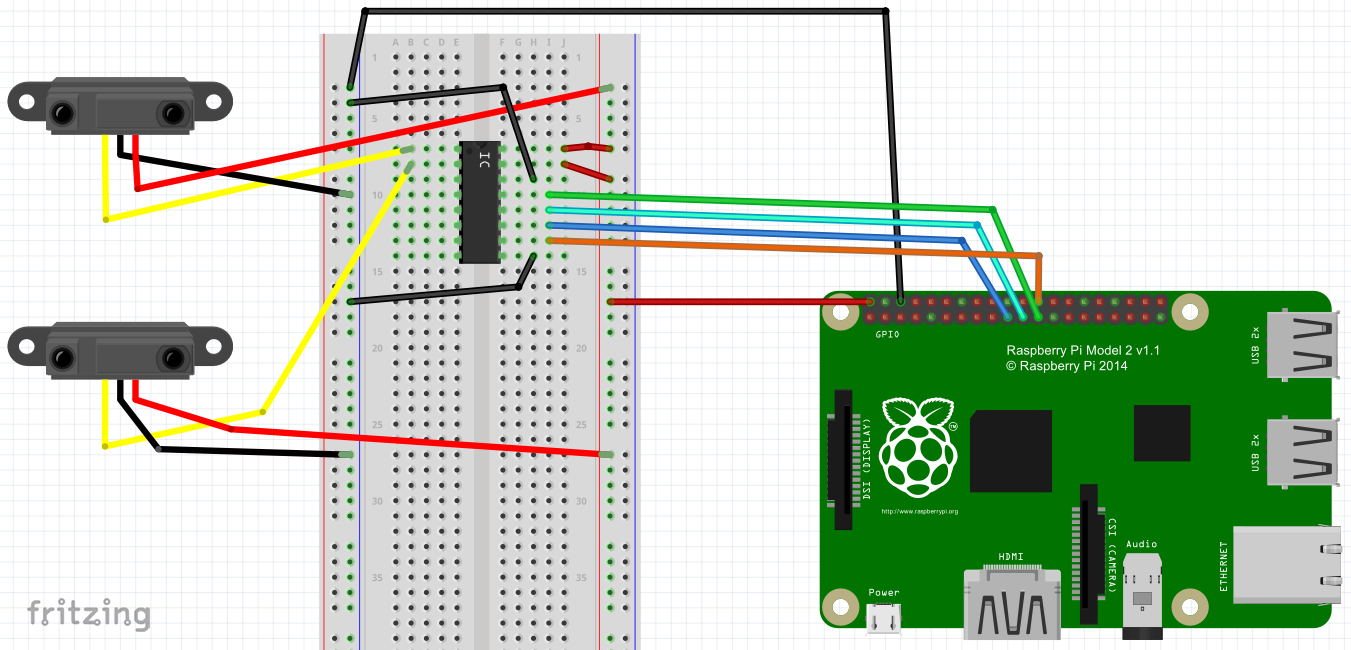
The smart mirror project recently entered the exciting part of working with hardware! The goal is to enable hand wave gesture recognition using two distance sensors placed on either side of the mirror. The first step is to get the data from the sensors and see how it looks like. In this blog post I wanted to focus specifically on connecting Raspberry Pi to the MCP3008 analog to digital converter using SPI, based on the Potentiometer Sensor Sample (on github). The code for this blog post is at github.com/AmadeusW/raspberryPiTest.
For the complete process of connecting distance sensors to Raspberry Pi, see my youtube podcast
 Smart Mirror episode 6 - Distance Sensor, ADC, SPI - circuit
 Smart Mirror episode 7 - Distance Sensor, ADC, SPI - code
 Smart Mirror episode 6 - Distance Sensor, ADC, SPI - circuit
 Smart Mirror episode 7 - Distance Sensor, ADC, SPI - code
A few pointers regarding the hardware
See Raspberry Pi 2 Pin Mappings and MCP3008 datasheet.
- Connect Pi
SPI MOSIto MCP3008Din, and PiSPI MISOto MCP3008Dout - initially I thought output of one device should be connected to the input of another device
- Use either Pi’s
SPI CS0orSPI CS1pin, you can pick one to use in the code - this means that you can independently connect two SPI devices
Connecting to SPI device
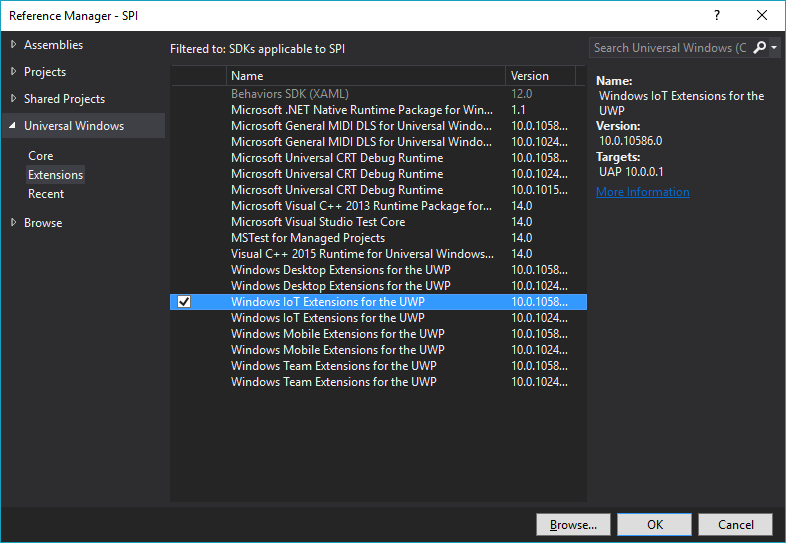
To connect to the ADC, you need to obtain an instance of SpiDevice from Widows.Devices.Spi namespace. To access this namespace, you need to first add a reference to “Windows IoT Extensions for the UWP”
Alright, let’s instantiate the SpiDevice. This code is adapted from the Potentiometer Sensor Sample.
This is boilerplate code where I would pay attention mostly to SpiConnectionSettings. The parameter is the Chip Select line you used in the circuit, and ClockFrequency should not exceed the maximum frequency specified by the device’s datasheet. I haven’t figured out Mode, but Mode0 seems to work for MCP3008.
SpiDevice ADC;
// . . .
var settings = new SpiConnectionSettings(0)                         // Chip Select line 0
{
    ClockFrequency = 500 * 1000,                                    // Don't exceed 3.6 MHz
    Mode = SpiMode.Mode0,
};

string spiAqs = SpiDevice.GetDeviceSelector("SPI0");                /* Find the selector string for the SPI bus controller          */
var devicesInfo = await DeviceInformation.FindAllAsync(spiAqs);     /* Find the SPI bus controller device with our selector string  */
ADC = await SpiDevice.FromIdAsync(devicesInfo[0].Id, settings);     /* Create an SpiDevice with our bus controller and SPI settings */
Getting data from the SPI device
Now here’s the real challenging code, and we’ll get into detail. Use TransferFullDuplex to read data from the SPI device. You pass in one byte array that tells the device what to do, and another empty array where device’s data will go.
byte[] request = new byte[3] { 0x01, 0x80, 0 };
byte[] response = new byte[3];
// . . .
ADC.TransferFullDuplex(request, response);
First, we need to establish the size of the arrays. Let’s start with the response buffer:
The ADC response is 10 bits long. We can fit it into 2 bytes. We also add one byte padding. Hence, the response is 3 bytes long.
In SPI communication, for every byte we want to receive, we send one byte. Therefore, the request bytes are also 3 bytes long.
Now, what do we send? The ADC datasheet calls for a 4 bit pattern 1000 to read from the first channel, and 1001 to read from the second channel.
A few pages further, the datasheet also says that the message needs to be preceeded with a 1 bit. So, to read values from the first channel, we send 11000.
Here is where various code snippets I found online get confusing: You can convert 11000 to hexadecimal 0x18. and 110000 to 0x30. Both approaches will work, but the code becomes not maintainable.
To address this issue, we just need to split the data into bytes in a different way: The first byte will contain the initial 1, and the second byte will contain the channel selecting pattern. Hence, we will send 0000 0001 1000 xxxx xxxx xxxx (x is don't care), which translates to { 0x01, 0x80, 0 }. Any change of the pattern will be reflected exclusively in the third hexadecimal digit (now 8).
Converting byte[] to int
Finally, we must convert the raw response of type byte[] to a more useful type, such as int. What happens in the ConvertToInt method, then?
int result = 0;
result = data[1] & 0x03;
result <<= 8;
result += data[2];
return result;
The datasheet of the ADC says that the device outputs 10-bit chunks of data. This code extracts these ten bytes from the input data array.
Let’s illustrate this code by plugging in values into variables. Suppose that byte[] data looks like this: AAAAaaaa BBBBbbbb CCCCcccc, and the ten bytes with actual data are bbCCCCcccc.
data[1] & 0x03becomesBBBBbbbb & 00000011, which is000000bbresult <<= 8transforms this into000000bb 00000000.result += data[2];produces000000bb CCCCcccc, which is the ten bits that we were after!
Conclusion
These were the biggest obstacles that I had when working with the SPI code. There is some non trivial math in this code, so feel free to comment below, or reach out to me on Twitter @HiAmadeus. To see how this code is used, watch Smart Mirror episode 7 - Distance Sensor, ADC, SPI - code.
Happy hacking!